
Comprehensive analysis on
Computer Network Technology
By God’s Will Obinna Ejianya
Figure 1.1
INTRODUCTION
The history of networking began with the human history because humans are social in nature. Humans have high tendency of seeking to connect with others either for exchange of goods and services or to exchange information – communication.
Over time the conventional way of exchanging communication between person to person or organization to organization has evolved immensely with more sophistication, speed and convenience.
This is as a result of the continuous inventions and improvement on Information networking Technology.
The tradition of people connecting with each other in family and community levels has existed since beginning of human existence. People always have need to connect with other people either for the purpose of passing information or for the purpose of selling information or commodities. Before the computer technology age, connecting with other people for any purpose has been limited to geographical distance since communication and connections were only done face to face.
Figure 1.2
Nowadays , computer technology has made connecting with other people and organizations more easier and faster. In fact, computer technology has evolved seriously over time and connecting with other people for social, commercial or any other reasons has been more diversified, dynamic, sophisticated and even faster. The problem and barriers of distance and location has been solved through Computer Network Technology. Computer network technology has immensely and positively changed the way we live. Our daily lives and activities have to involve the use of computer network technology in one way or the other. In fact we are almost dependent on the computer in every aspects of our lives including the way we do business, the way we interact and communicate with other people, health related services, transport systems, education systems, socializing and other aspects of our daily living.
Computer network system has been the basic platform or means through which we can be able to connect and communicate with other people and organizations in distant places in contrast to the old way of communicating through letter writing delivered by physical post office couriers, wired telephone calls or face to face communication which without the computer network technology can be very difficult, slow and expensive to facilitate.
Introduction to Computer Network Technology
Figure 2.1
Before we continue , we would like to look at the things that make up the Computer Network Technology by first of all introducing the Computer and Network Technology.
Computer is any programmed digital or electronic device that can be used to make calculations, take data input, process it and produce output of meaningful data or information. This includes mobile phones, calculators, ATM machines, laptops, desktop computers, PDA .. etc. A computer consists of hardware and software programs.
Network Technology is the use of computer devices and media to connect with other people, organizations or even other computers for the purpose of communication, business transactions, data storage, exchange of information and data, resource sharing, socializing.. etc.
Therefore, Computer Network Technology is a system of computers that are inter – connected using switches, routers and a channel or media for the purpose of communication, business transactions, data storage, exchange of information and data, resource sharing, socializing.. etc.
Computer Network Architecture
Topology
-
-
- Logical Topology
- Physical Topology
-
The Logical Topology of a network is the frame work of data flow within a network while Physical Topology lay out and arrangement of the computers and the connecting switches and intermediary devices that make up a network in designated locations within the network range. The computers, devices and the intermediary devices are also known as nodes. Example: computers, switches, hubs, printers etc.
There are different types of Physical and Logical Topology that a LAN network can be arranged. The physical connectivity of the computers, devices and inter-connection devices like switches and hubs can be arranged to appear in different shapes and locations and in this manner the topology of the network can be classified as the pattern of arrangement appears.
Example of Topology Types:
Figure 2.2

Types of Network Topology
-
-
- Point-to-point* Point-to-point topology arrangement is when nodes connects directly to each other and thereby sharing communication directly between each other.
- Bus* Bus topology is the arrangement where nodes connect to a single cable that runs in a straight way. Data and signals passing through the network from end to end can be accessed by any node connected to the network.
- Star* Star Topology is the arrangement where nodes are connected directly to a central switch serving as a central server to other nodes which serve as clients. Data signals sent to the network goes direct to the central switch and then searches for the MAC address of the destination node and sends the data direct to the node. If the address is not found then the data will be discarded.
- Ring* Ring Topology is the type of network physical arrangement that is in a circle form whereby nodes are connected from one to another in that form and data transfers goes from one node to another in the circle direction until it gets to the right address as destination.
-
-
-
- Mesh* Mesh Topology is the type of network arrangement whereby all nodes in the network are inter-connected to each other. This is used when there are many nodes in a network system.
- Tree
-
* Tree Topology is arrangement of network whereby nodes are arranged in a hierarchical order and one node serving as a root server for other nodes which are also connected to other nodes they serve as root. The network starts down from the root to other branches of nodes which connects to other nodes in hierarchical order.
TYPES OF NETWORKS
Computer Network can be in many types depending on the choice of network builder considering the following:
-
- Size of the areas intended to cover by the network.
- Size of space to deploy the network architecture.
- Intended number of users that can connect to the network.
- Purpose for which the network is being set up.
- Functions expected of the network.
- The affordable cost of setting up the network.
Local Area Networking (LAN)
A Local Area Network (LAN) is a group of computer end devices that are connected together through and sharing information and data within an organization. The LAN network is usually managed by the same organization and data sharing goes within the network. The LAN network is usually within the same geographical location since they are connected together through switches or bus, so it must be within a close range and they share the same server.
Figure 2.3
Wide Area Network
A Wide Area Network is a connection of Local Area Networks which are different geographical locations. The LANs are connected through the Telephone Service Providers which provide data lines to the owners of the LANs in different locations, so the data transmission passes through the TSP’s data line to locate the end nodes through their physical and Logical addresses. Organizations who have their branches in different countries can connect together through the WAN network.
Figure 2.4

Inter-Network (Internet)
The Inter-network or Internet is the connection of different LANs and WANs together through the media of networks which pass through intermediary devices like routers to connect to other networks. The Internet uses a data line connection on the physical media provided by the Internet Service Providers (ISP).
Figure 2.5

Components of Computer Network Technology
We will now talk about the intrinsic technology behind the Computer Network Technology, the way they process instruction, application or data input and transport it to the end device or destination user or network through specified medium of connection.
What are the components of the Computer Network Technology?
The components of Computer Network Technology which may be referred to as Networks or Network Technology are: Hardware, Software and Application Services, Protocols, Network Media and Intermediary devices.
- Computers – HardwareThe digital or electronic device (computer) hardware are the visible components of the network platform which include mobile phones, laptops, desktops. These are the containers of the software and programs that process applications and data transmission between computers and networks. The hardware is the end device or node that sends or receives data across the network.
- Software and applications
The software and application are the programs and services that run on the
network hardware /devices in order to facilitate effective communication between application
users. Example is when a user sends an Instant Message or Email to another device, node or
network, the software and application services are invoked to carry out the processes required
to enable the target host receive the data in the form the user expected.
- Protocols
Protocols are rules required for organized and effective decent communication between people
so that the essence of communication can be mutually understandable and meaningful. Without
proper rules, communication can be confusing and meaningless. In this regard, Computer
Network communication also apply rules to govern the way and characteristics in which
communication should be established effectively and meaningfully between computers and
networks. These protocols are embedded in the network devices by the manufacturers of the
devices following the organized rules to allow the device to communicate on a network.
The devices receive and pass further protocols to next nodes and intermediary devices through
the network interface of the device. Few examples of what the Protocols perform during
network communication are:
-
-
-
-
-
- The protocol layers format the data inputted by user and transmit it in a way it will be received and understood by the destination node or network.
- The protocol layer encodes into data those requirements and decode them at the receiving end.
- The protocol analyzes and determines the route and destination of the data transmitted.
-
-
-
-
- The Network MediumThe Network Media is the physical channel through which the devices are connected to other nodes (devices) or networks. Messages and other data are transported on the network from source user to destination user through the physical medium and then connect to the intermediary devices to pass the message to the destination computer or node. Currently there are three main types of media used for networking:- Copper- Fiber-Optic Cable-Wireless Media.
- Intermediary Devices.Intermediary devices are the devices that connect data from source computer devices to the destination computers or nodes. Examples of the intermediary devices are switches, hubs and routers. Switches and Hubs are used to connect computers within a Local Area Network (LAN), while routers are used for connecting other networks on Wide Area Network (WAN) or Inter-network.
The process that the computer networks undergo to pass and receive data to and from other computer networks is so complex and hard to understand because we do not see these processes and services going on inside the computer network system.
To explain the system of Computer Network Technology we have to use the engineering model of the Transmission Control Protocol (TCP) / Inter-network Protocol (IP) models and the referencing Open Source Interconnection (OSI) Model which are models use to explain the processes that the computer pass through in order to connect with other computer to achieve effective communication and transfer of data.
The Layer Models
In the computer networking technology, IT engineers use layered models to describe the complex process of network communication. There are protocols which can perform specific functions in the network system and these protocols are grouped as a well defined layers for the specific function.
The concept of Layered Models have some benefits that makes it very acceptable among the IT industry.
Benefits of the Layered Models concept
-
-
- The IT engineers that develop products that use functions of the layers can be able to understand specific function of each layer without mixing the functions up.
- Helps the IT devices manufacturers to be specific in developing specific equipment that works in a specific layer of the Network system.
- Gives a defined language and terms attributed to the specific layers of the Layered Models.
-
-
-
- Makes it easy for different manufacturers of the Network devices to understand the specific functions and can compete with each other. It reduces monopoly by device manufacturers.
-
Protocol and Reference Models
Protocol Models
Protocol Models are the set of protocol suites that are in a specific layer and perform specific rule or protocol in the network system. TCP/IP model is a protocol model that outlines the function of each layer of the model in the protocol suite. Example of the TCP is the User Datagram Protocol (UDP) used for video streaming and Voice over Internet (VoIP) and the IP addressing of the Network layer uses HTTP for web page content loading from the host server.
The Reference Model are meant for providing references for the consistent maintenance of the protocols and services that go on within the network system and data transmission and reception. The Reference Model major purpose to create a model that can allow the IT developers or engineers to understand the processes that go on within the Network System. The Reference Model does not give enough description or detailed information about the services of the Network Infrastructure. The Open Systems Interconnection (OSI) Model is the most well known Reference Model in Network Technology.
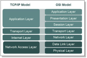
TCP/IP Model
The TCP/IP Model describes the Four Communication Protocol Functions of the Network Technology which are : Application, Transport, Internet and Network Access. The TCP/IP protocol ensures end to end delivery of transmitted data. It has connection and connectionless protols. The rules and and implementations of the TCP/IP Model were collectively developed by members of the Network and Inter-network industry using the Request for Comments (RFC) document which means that the documents can be accessed publicly. The RFC document standards and approval are maintained by the Internet Engineering Task Force (IETF).
TCP/IP Communication Protocols
TCP/IP Model
Figure 3.1
-
- Application*The Application layer has a protocol that represents application data to the user interface. Example of this Protocol is the HTTP which presents data of a requested web page to the user through the web browser application.
- Transport*The Transport Protocol suite supports communication between devices and performs error correction during transmission.
- Internet*The Internet Protocol suite uses the MAC and IP addressing in the Protocol Data Unit (PDU) to locate the correct route for data transmission to the right nodes or networks.
- Network Access*The Network Access Protocol suite controls the hardware devices and media through which data transmission gets to other networks or inter-networks.
The TCP/IP Model Communication Process
The TCP/IP Model protocol functions are implemented at both the sending and receiving ends to ensure the end to end transmission and receiving of data within the network and inter-networks.
The Communication Processes includes the following procedures:
- Creation of data at the application layer of the source end device.
- Data converted into segments and encapsulation takes place to further the encapsulated data down to next stack in the network communication system.
- Conveyance of the data to the appropriate media at the Network Access layer of the network.
- Transportation of the data through the inter-network via the media and intermediary devices.
- Receiving the data at the Network Access layer of the destination network or node.
- The data passes decapsulation and converted to original data the way it was from the source and then passed upwards to the next protocol up the network stack to the destination end device or node.
- The data is passed to the Application Layer and presented to the application used for the data by the end device or node.
The OSI Model
The Open Systems Interconnection (OSI) Model has seven layers which also can be referred to by number of the layer position. The Seven layers of the OSI Model in descending order are: Application, Presentation, Session, Transport, Network, Data-Link and Physical.
Unlike the TCP/IP Model, the OSI Model was developed by the International Organization for Standardization (ISO) as a model to provide a road map for further non proprietary developments in the Networking Technology. The OSI Model is a basic reference for networking professionals.
OSI Model
Figure 3.2
-
7. Application 6. Presentation 5. Session 4. Transport 3. Network 2. Data-Link 1. Physical
The Processes and Services within the OSI Model layers.
-
- Application*The Application layer is the layer where applications are run or used by end users. This is the layer that the end user sees and can input data and functions.
- Presentation*The presentation layer provides information about the data formats to the application of the end users. The presentation layer also performs data encryption and decryption for example, encrypted data will not be useful to the application end user unless the Presentation layer has decrypted it and presented to the application. Also, the Presentation layer identifies that a data is in image format or word processing format.
- Session*The Session layer’s main function is to manage sessions between users and services to be performed. For example, the session layer will be able to synchronize between different types of applications going on in the user application at the same time and manage them well so that they all goes on with their processes.
- Transport*The Transport layer converts data into segments, manages each piece of segment and then transports the data by end-to-end transmission method to ensure that it gets to the destination end device. The Transport layer also functions at the destination end device by converting the data segments into original data and moves it to the next stack up to the application of the destination end device.
- Network*The Network layer is where the data segments are created into packets and addressed to the destination end device, node, network or inter-network through intermediary devices. The same process is reversed at the destination end user.
- Data-Link*At the Data-Link layer, the packets of data are encapsulated into frames which contain the addressing PDU, Data and Error Correction PDU. The process is reversed at the destination network.
-
- Physical*The Physical layer is the media that receives the data frames and transmits it as binary data over physical channels between the nodes, networks and inter-networks. The process is reversed at the destination end device. There are three types of Media Specifications namely: Copper, Fiber-Optic, Wireless.
Network Addressing
In order to ensure successful and effective communication across the network, these conditions must be made known and true: A user sends message to a well addressed destination, the receiver has positioned a way to receive messages which are connected to the sender, message is controlled and passes through the defined media or channel to the destination and message is presented to the receiver in a well understandable way and safely. These conditions are the most important aspects of network system. Without proper addressing of end devices, data delivery will not be achieved and data will be lost in transmission.
Data addressing services and protocols take place in three different layers of the OSI Model. These layers are the Transport, Network and the Data-link layers. There are two types of addressing protocols that take place in the OSI Model: Logical Addressing System and Physical Addressing System. The Logical Addressing happens in the Transport and Network layer where address of the destination node or network is added at the PDU of the data. This address is then used by the PDU at the layers of the destination node or network. The Logical Address is usually the IP address of the end network or inter-network. Example of the IP addressing system is the Ipv4.
The Physical Addressing System happens also from the Transport layer where addressing is added to the PDU of the data segment and the address sorting done at the Data-Link layer to sort the physical address of the end nodes or devices in the network. The Physical address is the MAC (Media Access Control) address which is embedded at the Network Interface Card (NIC) of the devices in the network or inter-network. The NIC has MAC address placed on it by the manufacturers and devices are addressed by the MAC. The Physical addressing is mostly effective in a LAN Ethernet network or inter-network.
CONCLUSION
Computer Network Technology has really evolved over time and the speed at which it keeps changing and improving has really changed our world forever. Communication and connection with other people has been made more easier, faster and absolutely convenient. We can no more imagine a world without the Computer Network Technology because our social, health, political, business and many areas of our lives are dependent on the network technology.
References
1. William Stallings, Computer Organization and Architecture (Pearson Education, 2012)
2. W. Richard Stevens, TCP/IP Illustrated: The protocols, Volume 1 (Addison-Wesley Publishing Company, 1994)
3. Stephen Haag and Peter G. W. Keen,Information technology: tomorrow’s advantage today (McGraw-Hill, 1996)
4. Mark A. Dye, Rick McDonald and Antoon W. Rufi, Network Fundamentals: CCNA Exploration Companion Guide, Volume 1 (Cisco Systems, 2011)
5. Andrew S. Tanenbaum and David J. Wetheral, Computer Networks (Pearson Education, 2012)
6. Introduction to Networking Technologies ocument Number GG24-4338-00, 1994
http://www.redbooks.ibm.com/redbooks/pdfs/gg244338.pdf
Images and Diagrams
1. COmputer Network Technology Figure 1.1
http://educationcareerarticles.com/wp-content/uploads/2014/01/Computer-Networking.jpg
2. Human Network Figure 1.2
http://blog.etech7.com/Portals/153393/images/10061570_xxl.jpg
3. Different Computer Gadgets Network Figure 2.1
http://www.digitallanding.com/wp-content/uploads/2012/10/home-network-made-easy.jpg
4. Network Topology Figure 2.2
http://www.sensorsmag.com/files/sensor/nodes/2008/1530/Figure1.jpg
5. LAN Figure 2.3
http://2.bp.blogspot.com/-Jrm7b1FsU2U/UC0pH-tFXvI/AAAAAAAAAZQ/-lVZD42Fn4E/s400/LAN%2Bnetwork.jpg
6. WAN Figure 2.4
http://nevisblog.com/Photos/wan.jpg
7. Internet Figure 2.5
http://www.freetvconnection.com/wp-content/uploads/disgram-arrows.jpg
JLJL991, gotta admit, the number game is strong with this one. Haven’t dug too deep yet, but the site looks clean. Hoping the gameplay lives up to the first impression. Fingers crossed for some big wins! Spin to win: jljl991
Really interesting read! It’s good to see platforms prioritizing legal compliance & player safety – things like KYC are crucial. Checking if a nustar game login legit site is regulated gives me peace of mind. Great overview!
phjoylogin makes getting into your games a breeze. No need to struggle with complicated sign-ins, just quick and easy access to the fun. Seriously, check it out! phjoylogin
Responsible gaming is important for maintaining a healthy approach to entertainment.
It helps players remain focused and prevents unwanted risks.
By defining boundaries, individuals can enjoy gaming comfortably without overextending themselves.
Recognizing one’s habits encourages smarter behavior during gameplay.
Reliable platforms often promote useful tools that assist users in staying disciplined.
Maintaining balance ensures that gaming remains a rewarding activity.
For many players, responsible play helps maintain clarity while keeping the experience comfortable.
In the end, a thoughtful approach supports long-term well-being and keeps gaming safe.
https://dosweeps.com/faq
If you’re after a new gaming fix, cczzgame has got a solid roster. Had a good experience so far, plus they seem to be updating regularly. cczzgame